


Collision protection
Protection against collision with the gantry pillar
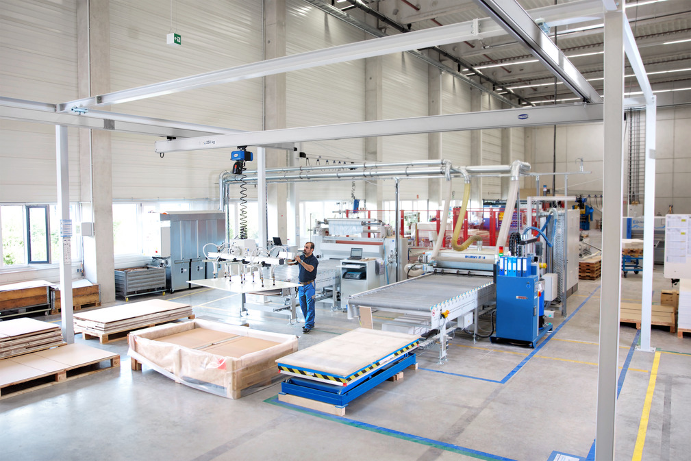
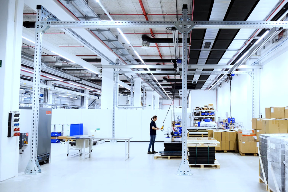
With the modular crane gantry KBG-G, Schmalz complements its product portfolio in the field of crane systems and thus supplies complete handling solutions from a single source. Customers benefit from a uniform and safe connection of the aluminum overhead crane system SRA . The crane gantry KBG-G fits perfectly into the overall system.
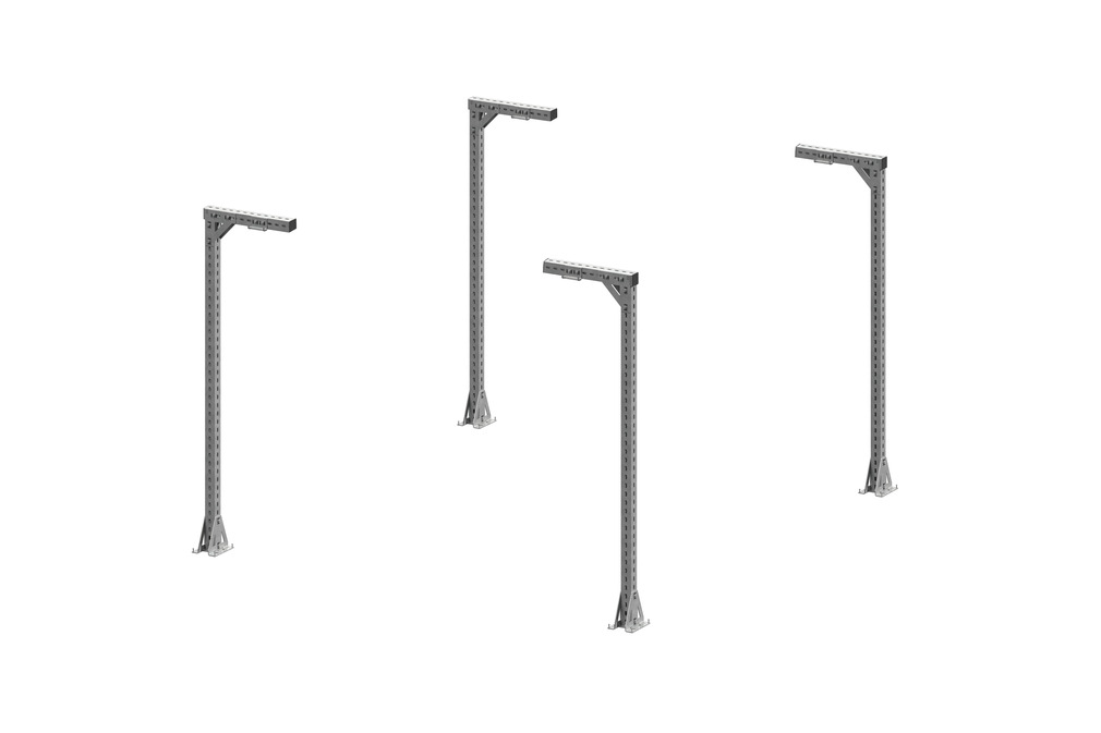
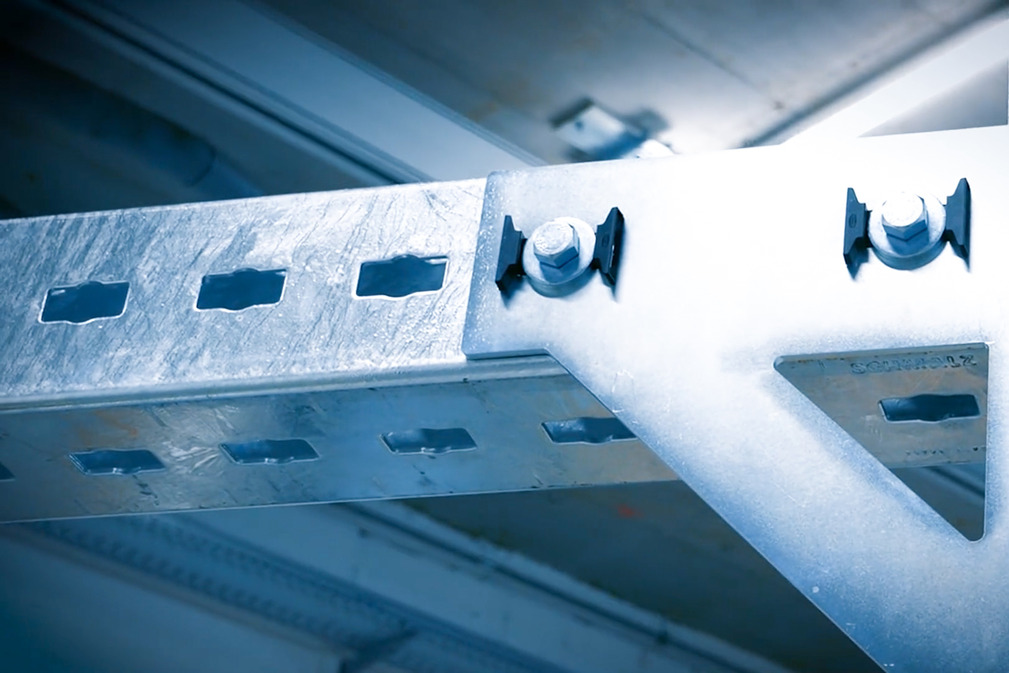
The proven Schmalz modular system is also used for the modular crane gantry KBG-G. The system for the modular crane gantry KBG-G consists of only twelve components. These components are combined with each other depending on the customer's application. The special feature: All connecting parts are attached to the profile with the same screw set, which simplifies assembly. In addition, only one profile size is used for the entire crane gantry KBG-G. A separate rolled profile with the corresponding holes for the screw set was developed for this purpose.
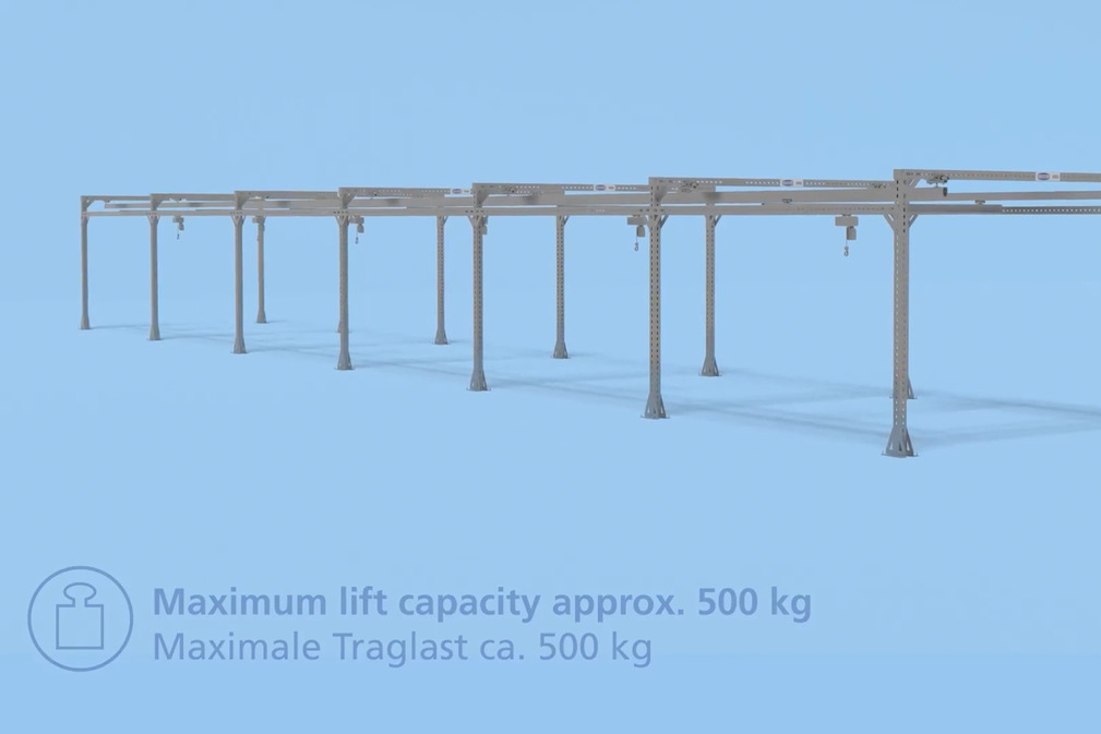
A Schmalz crane gantry KBG-G consists of at least two gates and can be extended by any number of gates in length. In this way, it can be optimally adapted to the Schmalz aluminum overhead crane system SRA.

Few components and modular design allow fast processing and short delivery times

Flexible integration into the existing production layout and easy adaptation and expansion in case of subsequent changes

Easy installation and mounting thanks to the screw set and the intelligent modular system

High level of safety thanks to independent strength calculation of the load-bearing components using the FEM method (designed in accordance with DIN EN 13001; stiffness class: HC3; S class: S3)

Robust surface protection due to the galvanized profile surface


Portal profile
In-house developed, hot dip galvanized rolled profile
Rastering in steps of 100 mm
Use for pillars, cross and longitudinal beams
Perforations provide connection of connecting plates with the screw set

Screw set
Connection of all connecting plates to the profile
Simple mounting of the connecting plates on the profile

Corner connection
Connection of pillar and cross beams
Connection of pillar and longitudinal beam at the first and last gate

Foot plate
Connection to the profile on both sides with two screw sets each
Alignment of the pillar with adjusting screws
Anchoring to the floor with two plugs per foot plate

Base plate
Base plate is inserted between the foot plates
Profile lies flat on the base plate

Suspension plate
Connection to the profile on both sides with two screw sets each
Connection of the overhead crane system with standard suspension for I-beams and T-beams (rigid and pendulum)

T-connection plate
Connection of two longitudinal beams to one pillar
Connection to the profile on both sides with six screw sets each

Cover cap
Cover of the ends of the cross beams
Visually appealing finish of the profile

Cable protection
Protection of the cable during entry and exit from the profile

(1) L = max. 8,000 mm
(2) B = max. 8,600 mm
(3) H = max. 5,560 mm
Maximum lift capacity: approx. 500 kg (workpiece weight and weight of lifting device)
The matching documentation for this product is available in this section.
| Documents | Language |
|---|
Discover application examples of the product in various industries - user-friendly, informative and practical.
No suitable videos found? Then take a look at our media center.Protection against collision with the gantry pillar

Direct mounting of the blower console to the profile with two screw sets
The screw sets are included in the set