Technologie vakuového upínání
- Technologie vakuového upínání pro procesně spolehlivé obrábění obrobků bez deformací v CNC obráběcích centrech
- Flexibilní upínací řešení pro zpracování dřeva, kovu a skla
Zobrazit kategorii
Vacuum clamping technology is a clamping technology in which workpieces are secured to a clamping surface using vacuum. The holding force results from the pressure difference between atmospheric pressure and the generated vacuum and acts uniformly across the entire effective clamping surface—without mechanical clamping points.
Unlike mechanical clamping methods, which apply forces at specific points via jaws, clamps, or screws, vacuum clamping technology distributes the holding force evenly. This enables distortion-free clamping and protects the workpiece surface.
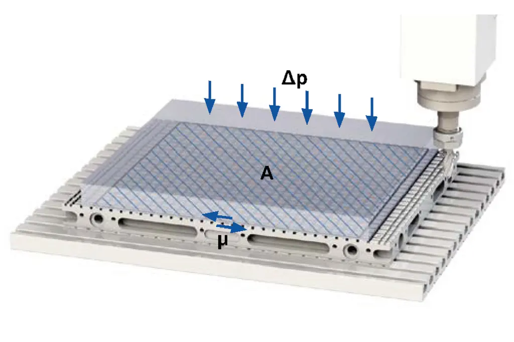
The horizontal clamping force of a vacuum clamping system—that is, the force that resists shear forces during machining—is determined by three factors:
Fh = A × Δp × μ
For every 100 mbar difference in pressure, a vertical clamping force of approximately 1 N/cm² results. Depending on the material and surface pairing, typical coefficients of friction range from approximately 0.2 to 0.5.
Since machining forces in practice act predominantly parallel to the workpiece surface, the horizontal clamping force is generally the decisive factor in the design of vacuum clamping systems. This is calculated by multiplying the vertical clamping force by the respective coefficient of friction.
A practical example: An aluminum workpiece with a clamping area of 600 cm² is clamped to a Matrix-Plate with friction islands (μ = 0.25) at a vacuum level of 800 mbar. The resulting horizontal clamping force is 1,200 N—sufficient for a chip removal rate of approximately 400 cm³/min during roughing.
The values provided are for illustrative purposes only, as the actual machining performance achievable in practice can vary significantly. Even dull tools, high feed rates, or unfavorable cutting parameters can significantly increase the machining forces
Vacuum clamping systems consist of several coordinated components for generating, distributing, and monitoring the vacuum.
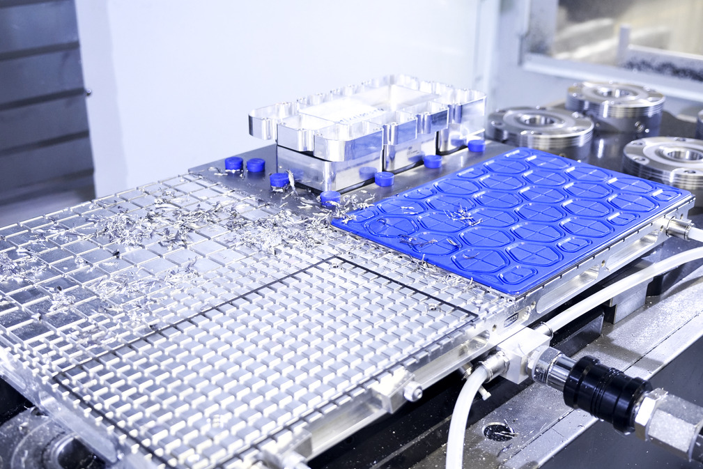
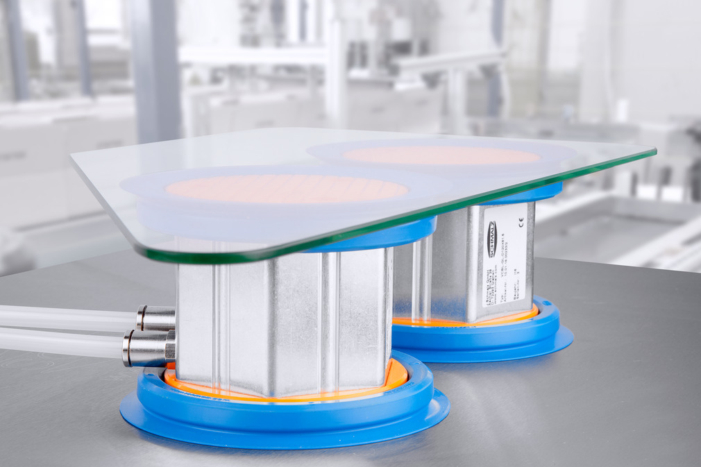
Vacuum clamping equipment forms the direct interface with the workpiece. Depending on the application, Matrix-Plates, vacuum suction cups, or clamping plates that suck through the vacuum are used, for example.
Vacuum generation occurs electrically or pneumatically. Depending on the application and process requirements, systems with high vacuum levels or high flow rates are used. In some cases, the vacuum generators also feature liquid separators or energy-saving controls.
The system is supplemented by accessories and add-on elements such as positioning and stop elements, vacuum monitoring, tubing, and components for vacuum distribution.
Vacuum clamping technology is suitable for workpieces with a sufficiently smooth and dense contact surface that allows for a stable vacuum. The method is material-independent and covers a wide range of applications.
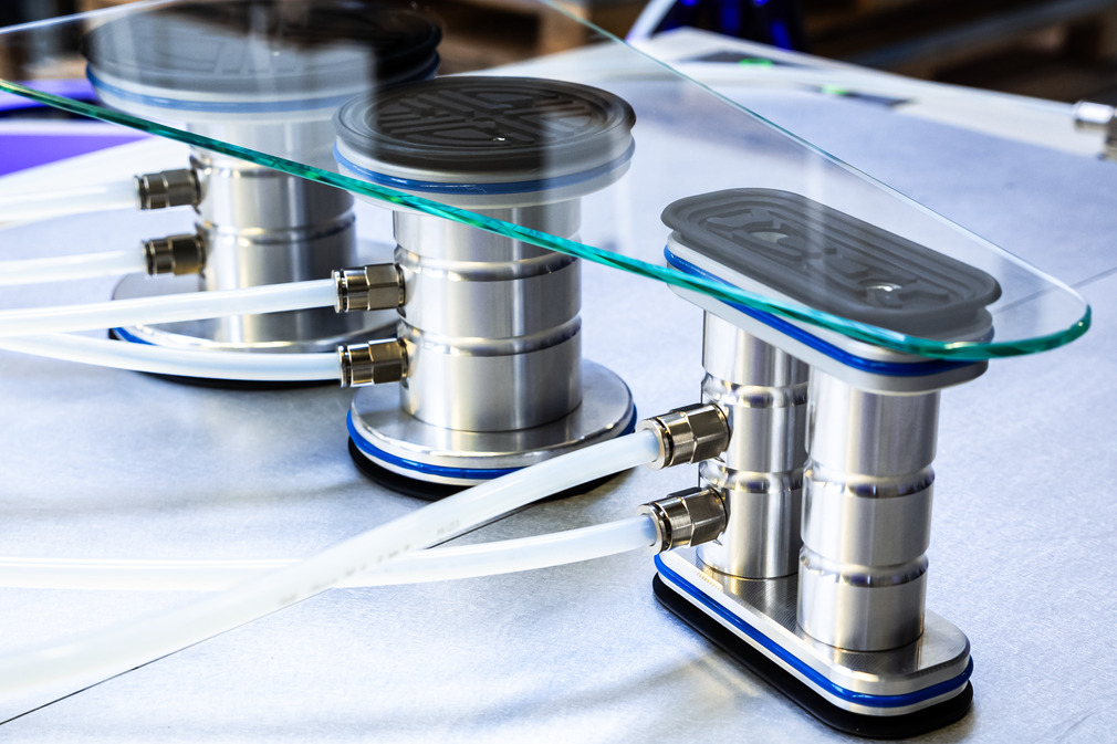
It has proven particularly effective in wood and glass processing. When working with glass, the uniform holding force prevents localized stress peaks that, due to the material’s brittleness, can lead to microcracks or breakage.
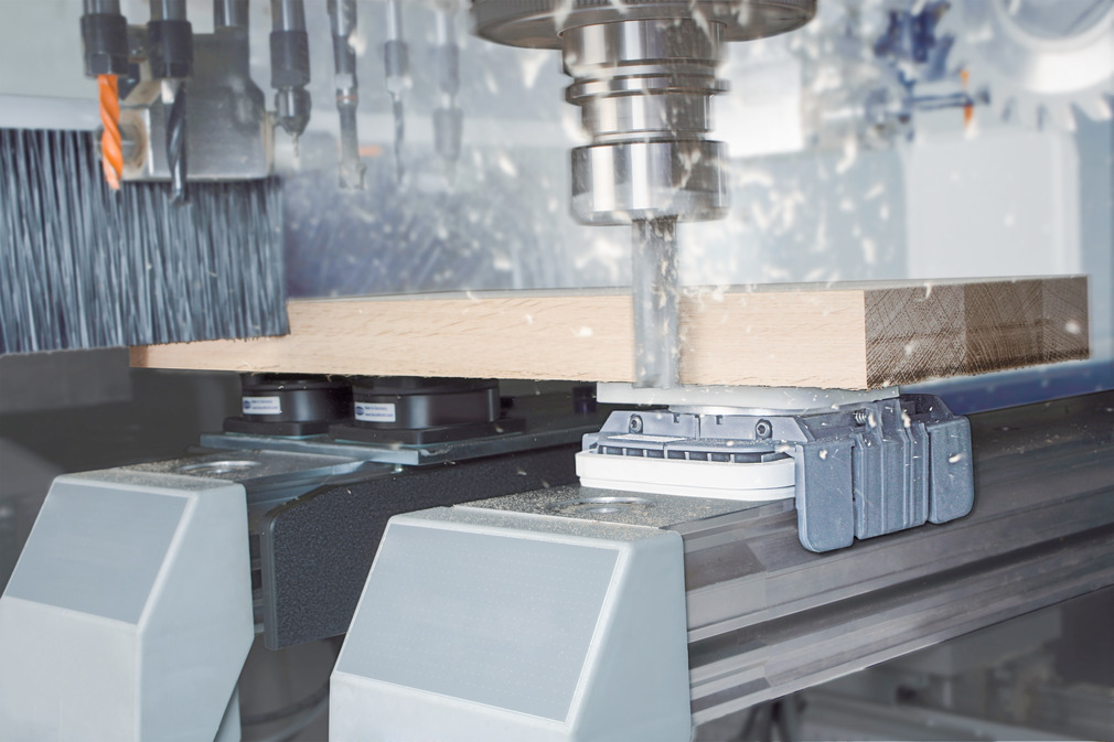
In wood working, damage caused by localized mechanical clamping forces is avoided. At the same time, the comparatively low clamping forces of the vacuum are sufficient for many wood-based materials, enabling short set-up times and flexible workpiece handling.
In plastics processing, the even distribution of force prevents deformation and protects sensitive surfaces from pressure marks.
In wood working, console table, grid table, and nesting table systems enable the quick and flexible clamping of large-area panel materials, for example in furniture production. Short set-up times and high flexibility offer advantages when dealing with varying workpiece geometries.
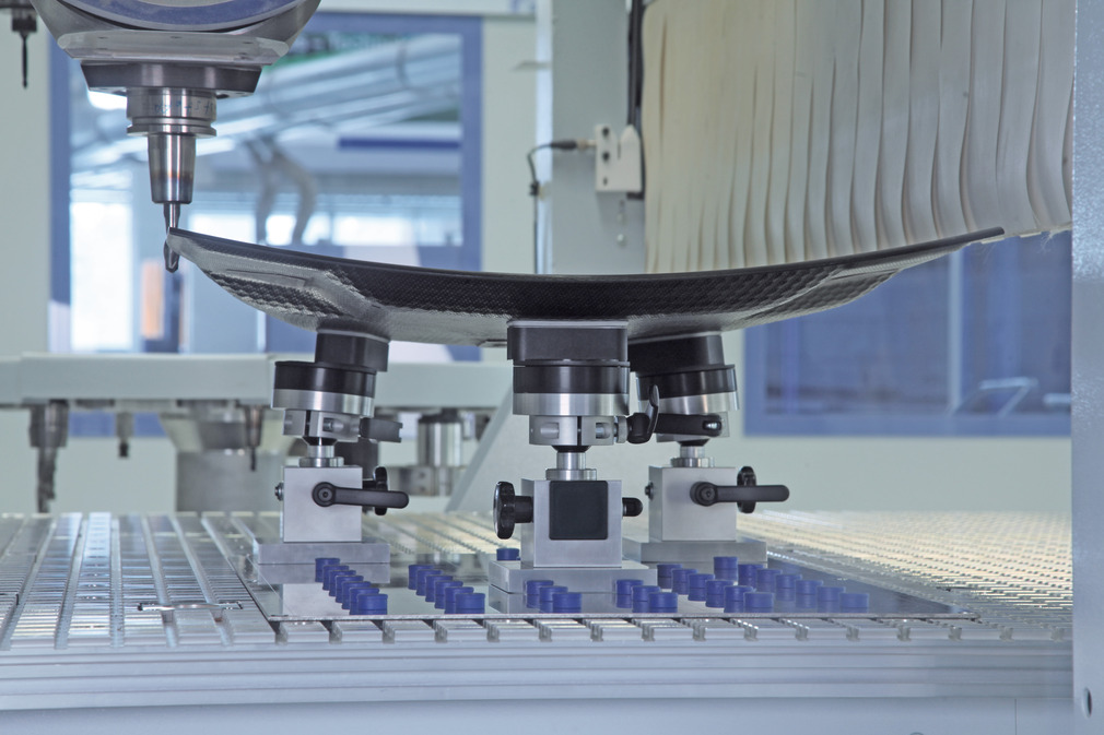
Vacuum clamping also offers advantages for thin-walled or large-surface-area metal workpieces made of aluminum or other non-ferrous metals. Workpieces can be clamped without warping, without lateral clamping elements restricting tool access or localized clamping forces causing deformation.

The achievable holding force depends directly on the tightness of the entire system. Only when there is a sufficiently tight seal between the workpiece and the clamping surface can the required vacuum be designed and maintained constantly during machining.
Even minor leakage or gaps lead to pressure losses and thereby reduce the transferable holding force. This has a particularly negative impact on process reliability when high machining forces or dynamic loads are involved.
In the case of porous materials, highly textured surfaces, or very small contact areas, the design to build up sufficient vacuum may be further limited. Workpieces with surface depths or irregularities exceeding approximately 0.1 mm therefore generally require adapted sealing lips or special contact surfaces to achieve sufficient holding forces.
In vacuum technology, leakage rates are specified as a flow rate in l/min. Even small leaks can reduce the achievable vacuum below the minimum value required for clamping.
If vacuum clamping alone is insufficient as a result, the machining strategy can be adapted—for example, by reducing the machining forces or increasing the effective clamping area, such as by cutting the workpiece out of the blank at a later stage.
Alternatively, the clamping can be further supported by mechanical stops or supplementary clamping elements.
Unlike mechanical clamping equipment, vacuum clamping technology does not apply localized forces but instead generates a uniform holding force across the entire surface. This is particularly advantageous when localized stress peaks would lead to workpiece warping, dimensional deviations, or surface damage.
In addition, the entire workpiece surface remains accessible, as no lateral clamping elements are required. This allows for machining on five sides in a single setup, which reduces the number of process steps.
The distributed force application also has a damping effect on vibrations. This can improve machining quality, particularly for thin or non-magnetic workpieces made of aluminum or plastics.
Furthermore, vacuum clamping systems can be flexibly adapted to different workpiece dimensions. This enables short set-up times and cost-effective production, particularly for small-batch production.
Unlike magnetic clamping technology, vacuum clamping is not limited to ferromagnetic materials. It can be used for wood, glass, plastics, aluminum, and other non-ferrous metals—anywhere where damage-free and low-distortion clamping is required.