


.jpg)

.jpg)

Find out more now
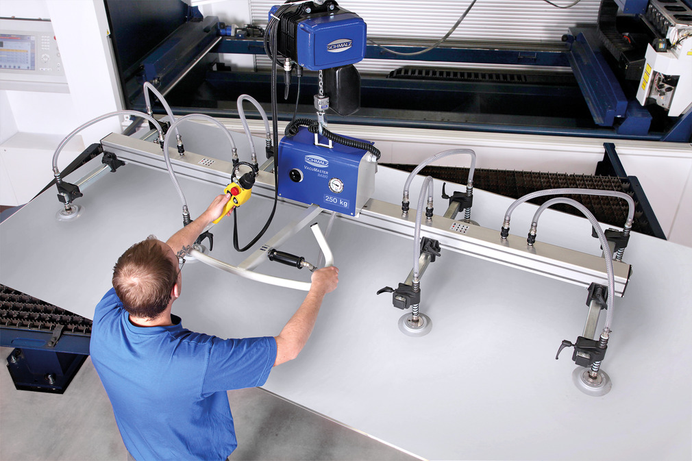
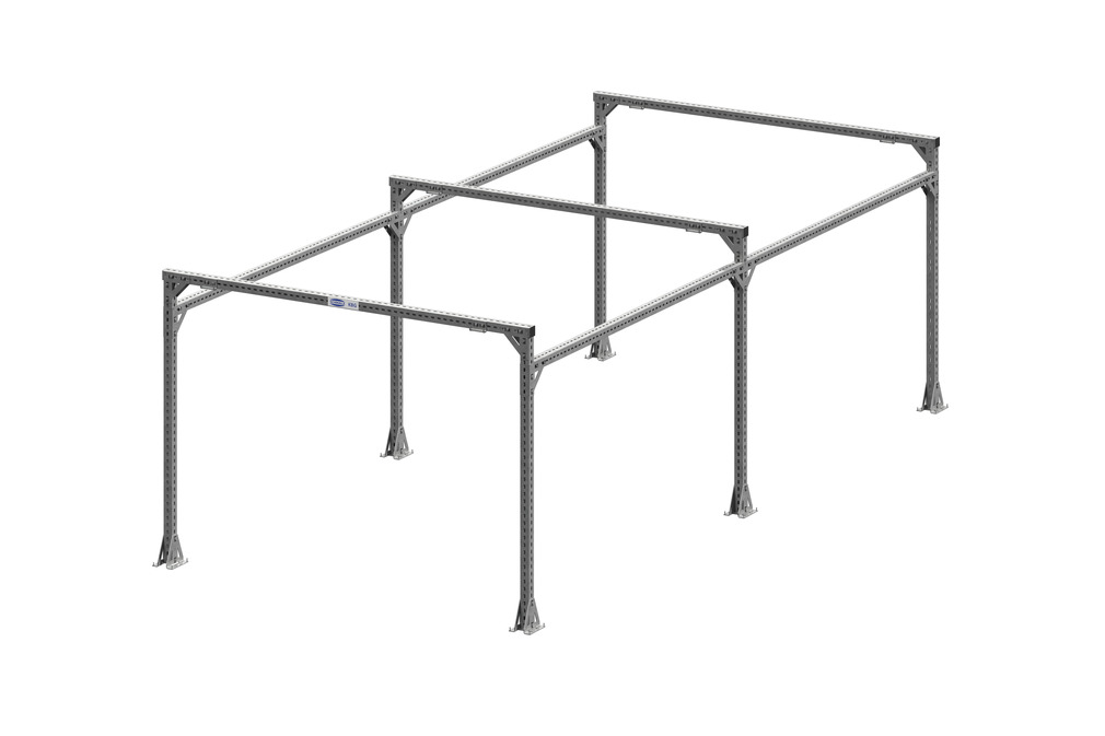
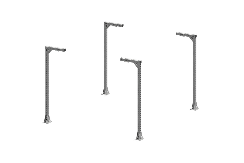
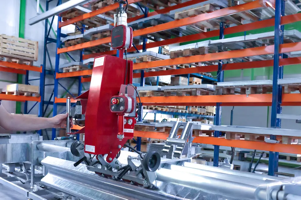
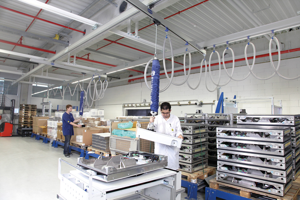
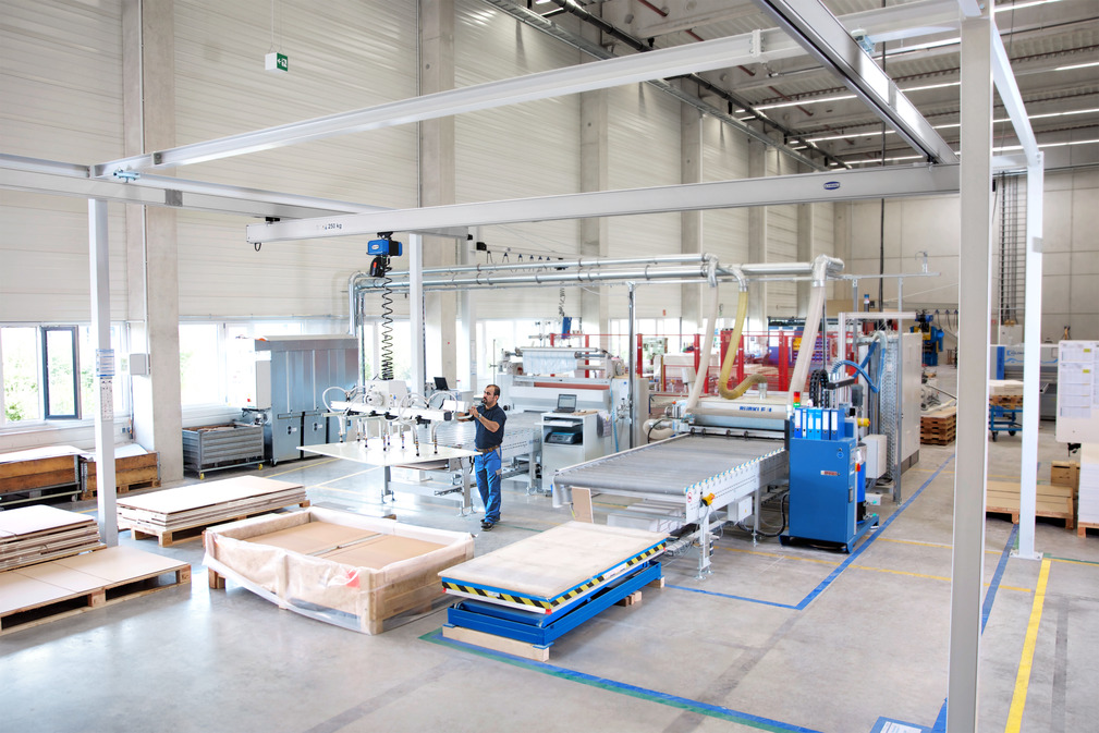
Schmalz aluminum overhead crane systems offer impressive low friction operation. A favorable weight-load ratio ensures that even heavy work pieces are handled effortlessly. The equal distribution of loads on all the supporting rollers prevents the transport trolleys from tilting. The modular design allows the crane system to be attached to any steel structure or other superstructure.
Ergonomic handling thanks to outstanding low-friction operation and low moving mass
Reduction of throughput times due to high working speed and positioning accuracy
Cost-efficient adaptation to individual requirements and lift capacities
Maximum safety through independent strength calculation of all load-bearing components according to the FEM method
Designed according to the latest state of the art (DIN EN 13001)
Awarded the seal of approval by Aktion Gesunder Rücken e. V.
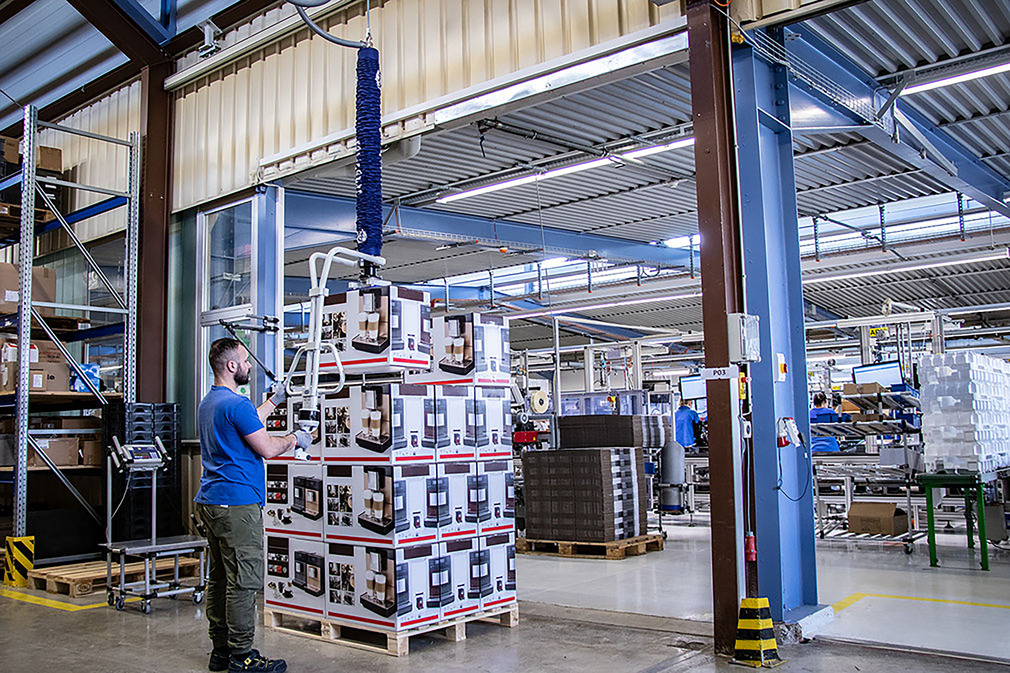
Schmalz vacuum lifters and crane systems support the back and musculoskeletal system when lifting light and heavy loads. They reduce strain and help to make the work environment ergonomic. This is confirmed by the independent association Aktion Gesunder Rücken e. V. (AGR) with its seal of approval.

.jpg)
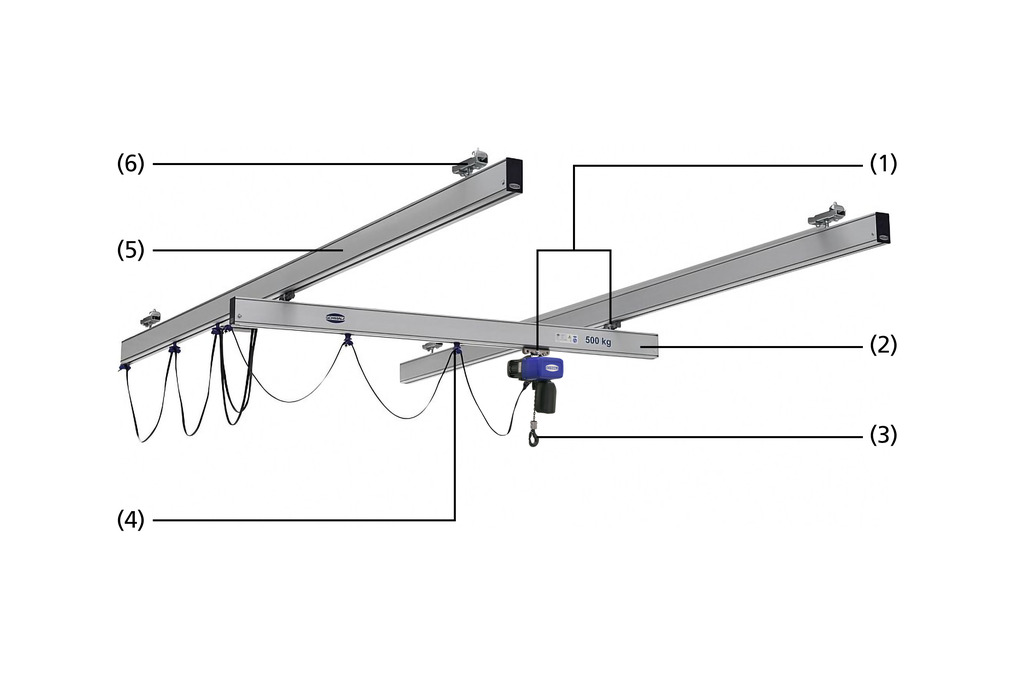
Lightweight and Robust Aluminum Profile
Weight optimized extruded profile with hollow chamber geometry (weight from 3 kg/m)
Inner web for reinforced vertical support
Material: Aluminum natural anodized (EN AW 60 63 T66)
Five profile sizes for loads weighing up to 1,200 kg
Profile lengths up to 8,000 mm can be extended as needed using rail connectors
Dovetail for retroactive mounting of variable end stops
Lateral grooves for connecting accessories
.jpg)
End plate
Attractive closing off of profiles
Protection from dirt
.jpg)
Reinforcement profile
Increases range and suspension distance by up to 50% while maintaining the same maximum load
Increases the maximum load for installed crane systems
.jpg)
Rail connector
Positive and non positive connection of profiles for crane runways or bridges larger than 8,000 mm
Full load capacity at the interface
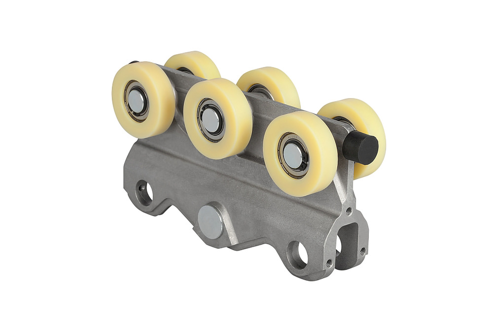
Transport Trolley with Optimal Running Performance
Stable aluminum pressure cast construction for loads weighing up to 1,000 kg
Only one transport trolley required to connect the crane bridge and hoist; thus less parts
Double transport trolley for loads weighing up to 1,200 kg
Optimal running performance thanks to large rollers made from high performance plastic
Upward and downward forces absorbed by only six rollers
Optimized for low ceiling heights thanks to its compact size
Eccentric pressure rollers to compensate vertical forces in telescopic booms
.jpg)
Crane bridge suspension element
Maximum load 2,000 kg
Swivel mounted as standard
Easy replacement of the joint
90° design for standard crane bridge; 0° design for telescopic rails
.jpg)
Fixed end stops
Prevents transport trolleys from falling out
Positive locking for maximum safety
Tool free mounting
.jpg)
Variable end stops
Easy adjustment of the crane bridge and hoist travel path
Demarcation of several working areas and the cable storage device
Can be mounted at a later stage
.jpg)
Antishock end stops
Gentle stopping of transport trolleys if end stops have to be reached e.g. for dynamic applications and telescopic jibs

Distance connectors
Stiffener for mounting rigid load and lifting axes
Available for all profile sizes
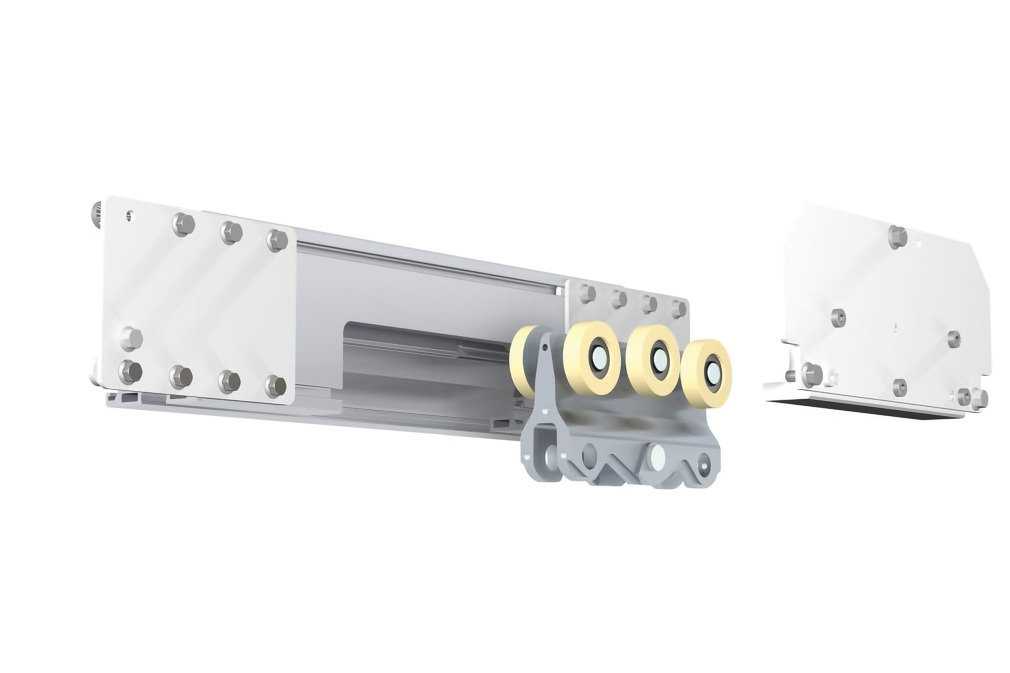
Service station
Easy replacement of transport trolleys, particularly for long crane systems and for crane systems with several crane bridges
Available for all section sizes
Fully resilient depending on the profile size
.jpg)
Low headroom module
Raises crane bridge to the level of the crane runway
Reduces the overall height of crane systems for low ceiling heights or transit roads

Spring return for telescopic jib incl. damping
Returns telescopic jibs after reaching into difficult to access areas
Optimal work flow thanks to the independent return of the jib
.jpg)
Safety cables
Further secures crane bridges, crane runways and hoists by means of steel cables
.jpg)
Suspended, height-adjustable
Most common suspension
Compensation of height differences in the ceiling structure by up to 30 mm
Rigid, height-adjustable
Absorption of upward forces for telescopes, lifting axes or manipulators
.jpg)
Rigid short 0°
Reduction of the overall height for low ceiling heights
.jpg)
Rigid short 90°
90° rotated design to reduce the overall height for low ceiling heights
.jpg)
Anchor plates for concrete ceilings
Special high-performance anchors with approval for dynamic loading
Required concrete quality C20/C25, concrete thickness min. 200 mm
.jpg)
Clasp for wooden girders and laminated beams
Safe mounting on wooden girders and laminated beams
.jpg)
Extension by up to 2,000 mm
Extension of the suspension to max. 2,000 mm for high ceilings
Diagonal brace required for stabilization
.jpg)
Diagonal suspension
Connection for ceiling structures with inclines greater than 8°
Diagonal brace required for stabilization
.jpg)
Conductor Line
Wireless energy supply for electrical devices supplied in the crane such as the chain hoist or vacuum lifting device
Profit from usable ceiling height as there are no cable storage devices or cable loops to cause interference
Ideal for crane systems with several bridges
Low surplus loading of the crane system thanks to lightweight plastic rails
Easy mounting thanks to adapted suspensions and spring loaded connectors for copper contacts
.jpg)
Trailing Cable
Most common form of energy supply via cable trolleys in the aluminum profile
Suitable for power cables (flat cables) and hoses (vacuum and compressed air)
Easy mounting thanks to pre-assembled cable trolley
.jpg)
Maximum dimensions: approx. 8 x 30 m
Maximum load: approx. 1,200 kg (depending on crane girder's own weight)
Weight of smallest crane profile: only 3,0 kg/m
Type | Height [mm] | Weight [kg/m] | Max. lift capacity [kg] | Area moment of inertia [cm4] lx | Area moment of inertia [cm4] ly | Moment of resistance [cm3] wx | Moment of resistance [cm3] wy |
|---|---|---|---|---|---|---|---|
SRA-100 | 100 | 3.1 | 125 | 89 | 112 | 21 | 25 |
SRA-105 | 105 | 5.5 | 250 | 244 | 253 | 48 | 51 |
SRA-140 | 140 | 7.8 | 500 | 384 | 651 | 92 | 77 |
SRA-180 | 180 | 9.2 | 800 | 457 | 1,283 | 145 | 92 |
SRA-220 | 220 | 10.7 | 1,200 | 544 | 2,281 | 207 | 109 |
SRA-80-V* | 80 | 4.1 | - | 144 | 177 | - | - |
*Reinforcement profile suitable for SRA-140, SRA-180 and SRA-220
The load diagram can be used for reference when selecting the profile size while taking a specific maximum load and the suspension distances into account. The suspension distances stated are based on a deflection of 1:300, the common value for calculating crane systems. Smaller deflection values such as 1:400 may be required for certain applications.
Example: With a maximum load of 200 kg and a predetermined suspension distance of 5,000 mm the profile SRA-140 is used. The maximum deflection is then 17 mm (5,000 mm / 300).
Type | Height [mm] | Length [mm] | Width [mm] | Weight [kg] | Max. lift capacity [kg] | Max. lift capacity [kg] |
|---|---|---|---|---|---|---|
Transport trolley | 125 | 240 | 55 | 1.4 | 1,000 | 1,000 |
Double transport trolley | 150 | 500 | 75 | 6.5 | 1,200 | 1,200 |
*Subject to technical changes without notice